Automated Nerf Gun Turret
Hardware
Mechanical
Prior to my Fall 2020 semester at MIT, I had no experience at all with CAD. I took a 6-unit course called 15.S20 Design for 3D Printing which gave me a good run through of 3D design techniques. I am by no means a mechanical engineer, and probably never will be, but my elementary CAD skills were enough for this project.
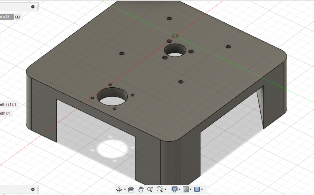
Here is the base, which consists of two large holes surrounded by mounting holes: one for the stepper motor and the other for the wires from the main assembly. Notice that the smaller hole (wires) has the 4 mounting holes for the lazy susan in addition to 3 holes arranged in a triangle. The three holes are (or rather, were supposed to be) for a slip ring. More on this later.
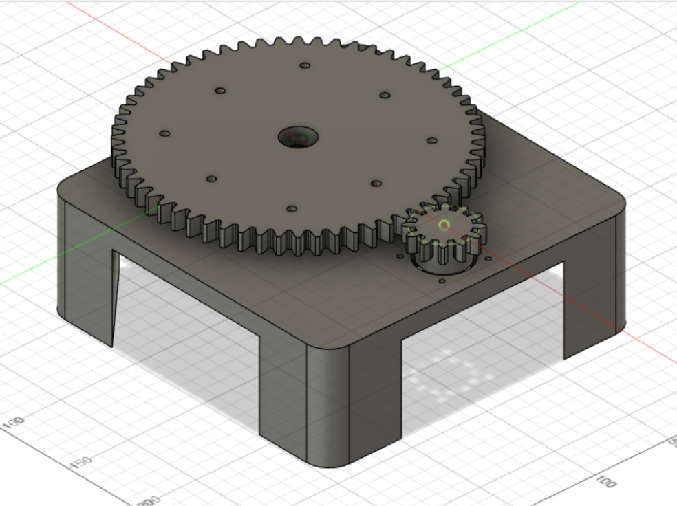
On top of the base is this set of gears which provides more torque from the stepper motor through a 5:1 gear reduction. This ends up being quite important since the top half is almost 4lbs heavy.
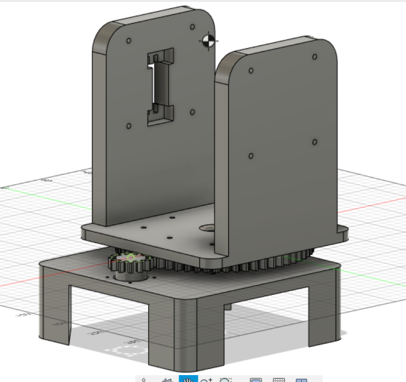
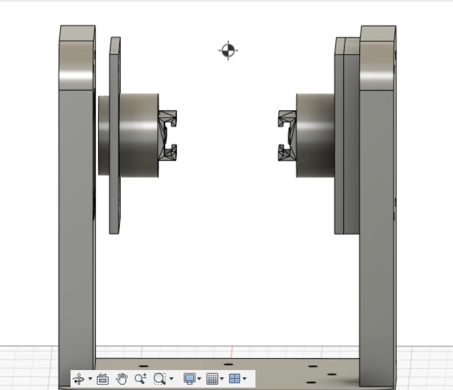
Mounted on the gears is the walls, which are used to hold the nerf gun up. Notice that the left wall has a slot cut out from it; this is used to mount the servo which controls the angle of the nerf gun.
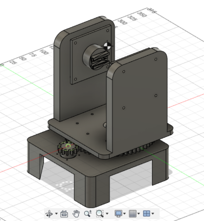
And finally, mounted on the walls through the set of lazy susans is the gun mount. I took advantage of NERF’s tactical rail system and simply printed the railing onto some cylinders. Also note that the left mount is slightly extended; this is to interface with the servo on the wall.
Electrical
On the electronics side of things, the turret uses an Arduino Nano hooked up to a stepper motor driver (for the gears), the servo, and to two relays (for the flywheel and the pusher on the nerf gun).
A problem
Initially, I used a slip ring that passes through the center of the turret
I should’ve seen this coming, but there was too much noise in the slip ring to transfer USB 2.0 webcam data through.
I resolved this issue by simply removing the slip ring and running the wires straight through the hole.
This does mean that the turret will tangle itself in its own wires after a few revolutions, but this ends up not being
an issue at all most of the time.
Software
Now that the hardware was assembled, it was time to program the turret. On the macro scale, the arduino receives control signals over serial from a computer vision script on my laptop.
Arduino-side
The arduino code is extremely simple; it decodes characters over serial and applies the given command to the motors. It is short enough to be displayed here in its entirety:
// Include the AccelStepper library:
#include <AccelStepper.h>
#include <Servo.h>
// Define stepper motor connections and motor interface type.
// Motor interface type must be set to 1 when using a driver:
#define dirPin 2
#define stepPin 3
#define flywheelPin 4
#define pusherPin 5
#define motorInterfaceType 1
#define servoPin 8
// Create a new instance of the AccelStepper class:
AccelStepper stepper = AccelStepper(motorInterfaceType, stepPin, dirPin);
Servo servo;
bool usingRunSpeed = false;
void setup() {
  Serial.begin(9600);
  pinMode(flywheelPin, OUTPUT);
  pinMode(pusherPin, OUTPUT);
  // Set the maximum speed and acceleration:
  stepper.setMaxSpeed(10000);
  stepper.setAcceleration(3000);
  servo.attach(servoPin);
  servo.write(110);
}
void loop() {
  if (Serial.available() > 0) {
    String in = Serial.readStringUntil('\n');
    switch(in.charAt(0)) {
      //runspeed?
      case 'm':
        usingRunSpeed = true;
        break;
      case 'M':
        usingRunSpeed = false;
        break;
      //stepper
      case 's':
      {
        float newSpeed = in.substring(1).toFloat();
        stepper.setSpeed(newSpeed);
        Serial.println("Stepper speed set");
      }
        break;
      // stepper to position
      case 'T':
      {
        float absolutePos = in.substring(1).toFloat();
        stepper.moveTo(absolutePos);
        Serial.println("Stepper pos set");
      }
        break;
      //Servo
      case 'S':
      {
        float newAngle = in.substring(1).toInt();
        servo.write(newAngle);
        Serial.println("Servo angle set");
      }
        break;
      case 'F':
        digitalWrite(flywheelPin, HIGH);
        Serial.println("Flywheel pin set high");
        break;
      case 'f':
        digitalWrite(flywheelPin, LOW);
        Serial.println("Flywheel pin set low");
        break;
      case 'P':
        digitalWrite(pusherPin, HIGH);
        Serial.println("Pusher pin set high");
        break;
      case 'p':
        digitalWrite(pusherPin, LOW);
        Serial.println("Pusher pin set low");
        break;
      default:
        Serial.println("unknown command");
    }
  }
  if (usingRunSpeed){
    stepper.runSpeed();
  } else {
    stepper.run();
  }
}
Computer-side
I used the python API available from OpenPose to detect people in the camera frame. The system uses a PID controller to manipulate both the stepper motor and the server motor to keep the center of the camera aligned with the center of mass of the person. This code is also extremely short; the majority of the code is merely setup.
Here is the important part (camera loop):
while True:
    if not video_capture.isOpened():
        print("Unable to load camera")
        sleep(5)
        pass
    ret, frame = video_capture.read()

    # Process frame
    datum = op.Datum()
    datum.cvInputData = frame
    opWrapper.emplaceAndPop(op.VectorDatum([datum]))
    output_frame = datum.cvOutputData[:,:,:]
    if datum.poseKeypoints is not None:
        if datum.poseKeypoints[0][1][2] > 0:
            neck_x, neck_y, neck_score = datum.poseKeypoints[0][1]
            if abs(neck_x - WIDTH/2) < ATTACK_MARGIN and abs(neck_y - HEIGHT/2) < ATTACK_MARGIN:
                set_flywheel_on()
                if first_lock_time is None:
                    first_lock_time = datetime.datetime.now()

                if (datetime.datetime.now() - first_lock_time > datetime.timedelta(seconds = 0.3)):
                    set_pusher_on()
                    if not pygame.mixer.music.get_busy():
                        pygame.mixer.music.play()

                    cv2.circle(output_frame, (int(neck_x), int(neck_y)), 20, (0, 0, 255), -1)
                else:
                    cv2.circle(output_frame, (int(neck_x), int(neck_y)), 20, (255, 0, 0), -1)
            else:
                first_lock_time = None
                cv2.circle(output_frame, (int(neck_x), int(neck_y)), 20, (0, 255, 0), -1)

                set_flywheel_off()
                set_pusher_off()
            new_speed = stepper_pid(neck_x)
            if abs(new_speed) < 100:
                new_speed = 0
            set_stepper_speed(new_speed)

            # Servo
            new_angle_delta = servo_pid(neck_y)
            angle += new_angle_delta
            angle = max(100, angle)
            angle = min(140, angle)
            set_servo_angle(angle)
        else:
            first_lock_time = None
            set_pusher_off()
            set_flywheel_off()

            nonzero = datum.poseKeypoints[0, :, 2] > 0
            nonzero_keypoints = datum.poseKeypoints[0, nonzero, :]
            if nonzero_keypoints.any():
                x, y, a = nonzero_keypoints[0]
                new_speed = stepper_pid(x)
                if abs(new_speed) < 100:
                    new_speed = 0
                set_stepper_speed(x)
    else:
        first_lock_time = None
        set_pusher_off()
        set_flywheel_off()

    ...
Although the implementation is simple, the results are surprisingly good.